Cfd simulation of vortex shedding
From CFD-Wiki
(→Example of 2 Dimensional Problem) |
(Sent in better images) |
||
| Line 4: | Line 4: | ||
==Example of 2 Dimensional Problem== | ==Example of 2 Dimensional Problem== | ||
| - | The images below were created for the case of 2-D flow past a square obstruction with a [[Reynolds number]] of 1000 and freestream boundary conditions on the top, bottom, and right boundaries. The quantities of the Navier-Stokes equations were non-dimensionalized and the [[Schemes_by_Leonard_-_structured_grids|QUICKEST]] finite differencing algorithm by B.P. Leonard was used. The grid was uniform with 102 | + | The images below were created for the case of 2-D flow past a square obstruction with a [[Reynolds number]] of 1000 and freestream boundary conditions on the top, bottom, and right boundaries. The quantities of the Navier-Stokes equations were non-dimensionalized and the [[Schemes_by_Leonard_-_structured_grids|QUICKEST]] finite differencing algorithm by B.P. Leonard was used. The grid was uniform with either a 204 x 90 node mesh or a 102 x 45 node mesh. |
<br> | <br> | ||
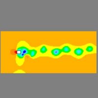
| - | [[Image:vortex_prs.jpg|thumb|200px|left|pressure at | + | [[Image:vortex_prs.jpg|thumb|200px|left|pressure at 95.4s and 3180 timesteps.]] |
<br> | <br> | ||
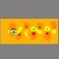
| - | [[Image:vortex_vx.jpg|thumb|200px|left|velocity x at | + | [[Image:vortex_vx.jpg|thumb|200px|left|velocity x at 95.4s and 3180 timesteps.]] |
<br> | <br> | ||
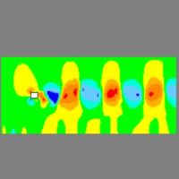
| - | [[Image:vortex_vy.jpg|thumb|200px|left|velocity y at | + | [[Image:vortex_vy.jpg|thumb|200px|left|velocity y at 95.4s and 3180 timesteps.]] |
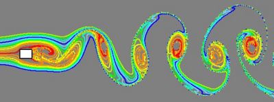
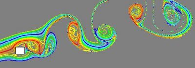
| - | [[Image:Vortex_streaklines-0ang.jpg|400px|thumb|center|[[streaklines]] at | + | [[Image:Vortex_streaklines-0ang.jpg|400px|thumb|center|[[streaklines]] at 96s and 2400 timesteps for 0 angle of attack flow.]] |
<br> | <br> | ||
<br> | <br> | ||
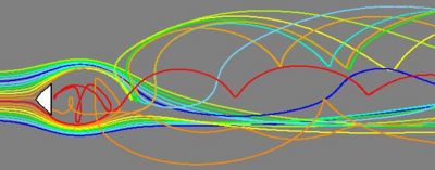
| - | [[Image: | + | [[Image:Vortex_pathlines-0ang.jpg|400px|thumb|center|[[pathlines]] at 96s and 2400 timesteps for 0 angle of attack flow.]] |
<br> | <br> | ||
<br> | <br> | ||
Revision as of 23:58, 18 April 2008
To numerically simulate vortex shedding, CFD is used to calculate the unsteady flow that arises from a fluid moving past an obstruction. Downwind of the obstruction are regions of lower pressure which causes the fluid which initially was deflected around the obstruction to get sucked into these regions, begin to circulate, and form vortices.
For a Newtonian fluid, it is sufficient to use the Navier-Stokes equations as the governing equations, and choose either the finite element method, FEM, or finite differencing, FD, to do the simulation. Vortex shedding is more likely in incompressible fluids than compressible fluids, so the former is used when capturing this phenomenon. Although both types of fluids are represented by the Navier-Stokes equations, their methods of solution differ significantly. For instance, when using FD for incompressible fluids, it is common to have an explicit expression for the velocity as you integrate the equations in time. In compressible fluids, the governing equations are often written in terms of the conservative form of Euler's equation, with velocity and pressure extracted from the conserved quantities(e.g. mass, momentum, energy). Also, compressible flows usually involve the calculation of additional quantities such as density and temperature.
Contents |
Example of 2 Dimensional Problem
The images below were created for the case of 2-D flow past a square obstruction with a Reynolds number of 1000 and freestream boundary conditions on the top, bottom, and right boundaries. The quantities of the Navier-Stokes equations were non-dimensionalized and the QUICKEST finite differencing algorithm by B.P. Leonard was used. The grid was uniform with either a 204 x 90 node mesh or a 102 x 45 node mesh.
Pressure Corrector
The incompressibility of the fluid is enforced through the continuity equation using pressure as a corrective quantity whose gradient in either the x or y direction is added to the velocity in the respective direction. Calculating the pressure correction involves solving the discrete Poisson equation for pressure.
Staggered grid
Use of a staggered grid, where pressure and velocities in the x and y directions are calculated at alternating grid points, is commonly used with upwinding to avoid oscillatory behavior.
See also
References
- Davis, R. W., and E. F. Moore, A numerical study of vortex shedding from rectangles, Journal of Fluid Mechanics, 116, 475 (1982).
- Davis, R. W., E. F. Moore, and L. P. Purtell, A numerical-experimental study of confined flow around rectangular cylinders, Physics of Fluids, 27, 46 (1984).
- Hoffman, Joe D., Numerical Methods for Engineers and Scientist, fourth edition , McGraw-Hill Inc., New York, 1992.
- Leonard, B. P., A stable and accurate convective modelling procedure, Computer Methods in Applied Mechanics and Engineering, 19, pages 59-98 (1979).

